Review Chap 5
-
ISA(omit)
The ISA specifies all the information about the computer that the software has to be aware of.
The ISA specifies the memory organization, register set,and instruction set,including the opcodes, data types, and addressing modes of instructions in the instruction set.
There are 65536 memory locations in LC-3, and 8 registers. We refer to 16 bits as one word, and we say the LC-3 is word-addressable.
Each register in the set is called a general purpose register(GPR).
Register file: what does every register contain.
-
The instruction set: defined by its set of opcodes, data types and addressing modes.
The addressing modes determine where the operands are located. The data type is the representation of operands in 0s and 1s.
Opcodes
- Some ISAs have a very large number of opcodes, one for each of a very large number of tasks that a program may wish to carry out.
- There are three different types of instructions, which means three different types of opcodes: operates, data movement, and control.
- Operate instructions process information.
- Data movement instructions move information between memory and the registers and between registers/memory and input/output devices.
- Control instructions change the sequence of instructions that will be executed.
Data Types
- Every opcode will interpret the bit patterns of its operands according to the data type it is designed to support.
Addressing Modes
- An addressing mode is a mechanism for specifying where the operand is located.
- LC-3 supports five addressing modes:
- immediate/literal (the same)
- register
- 3 memory addressing modes:
- PC-relative
- indirect
- Base+offset
-

- Condition Codes(CC)
- The LC-3 has three single-bit registers that are individually set (set to 1) or cleared (set to 0) each time one of the eight general purpose registers is written into as a result of execution of one of the operate instructions or one of the load instructions.
- Each operate instruction performs a computation and writes the result into a general purpose register.
- Each load instruction reads the contents of a memory location and writes the value found there into a general purpose register.
- The three single-bit registers are called N, Z, and P, corresponding to their meaning: negative, zero, and positive. And their value will be modified each time a GPR is written by an operate or a load instruction.
- They are referred to as condition codes because the condition of those bits are used to change the sequence of execution of the instructions in a computer program. (e.g.
BR's condition.)
结果我研究每个指令的数据通路又给我绕晕了。。。我是真菜
- Operate Instructions
ADD,AND, andNOT- The
NOT(opcode = 1001) instruction is the only (in LC-3) operate instruction that performs a unary operation. See docs for details.
- Inmmediates

- Since the immediate operand havs a size less than a word, so not all 2's complement integers can be immediate operands.
- The LEA Instruction (Although Not Really an Operate)
- It does not really operate on data, it simply loads a register with an address. It clearly does not move data from memory to a register, nor is it a control instruction. We had to put it somewhere, so we chose to discuss it here! See docs for details.

- We shall see shortly that the LEA instruction is useful to initialize a register with an address that is very close to the address of the instruction doing the initializing.
- Data Movement Instructions
- We will ignore for now the business of moving information from input devices to registers and from registers to output devices which will be an important part of Chapter 9. In this chapter, we will confine ourselves to moving information between memory and the general purpose registers.
- The process of moving information from memory to a register is called a load.
- The process of moving information from a register to memory is called a store.
- In both cases, the information in the location containing the source operand remains unchanged.
- In both cases, the location of the destination operand is overwritten.
- The LC-3 contains six instructions that move information:
LD,LDR,LDI;ST,STR,STI.

- Data movement instructions require two operands, a source and a destination.
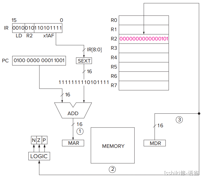
- PC-Relative Mode
LDandSTspecify the PC-relative addressing mode.
- Indirect Mode
LDIandSTIspecify the indirect addressing mode that means the address of the address of the operand to be loaded or stored.
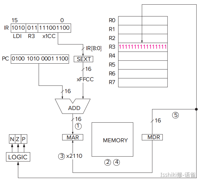
- 在寻址过程中进行一次迭代,用 C 的
[]符号写的话感觉就像是mem[ mem[idx] ]。 - Base+offset Mode
LDRandSTRspecify the Base+offset addressing mode. The Base+offset mode is so named because the address of the operand is obtained by adding a sign-extended six-bit offset to a base register.
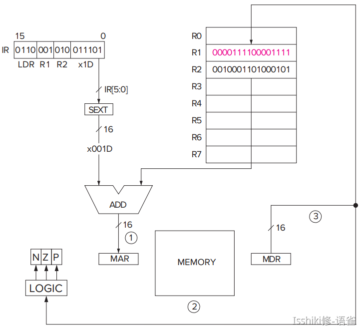
- Note that the Base+offset addressing mode also allows the address of the operand to be anywhere in the computer's memory.
- 所以因为这个特性,这种寻址模式是在长距离跳转中较为实用的。
Control Instructions
The LC-3 has five opcodes that enable the sequential execution flow to be broken:
- conditional branch
- unconditional jump
- subroutine call (sometimes called function)
TRAP(service call)RTI(Return from Trap or Interrupt)
Two Methods of Loop Control
- loop body & iteration fo the loop body
- Loop Control with a Counter
- Loop Control with a Sentinel
- We append to our sequence of values to be processed a value that we know ahead of time can never occur (i.e., the sentinel).
- 就是需要一个哨兵标记序列的尾部,当访问到该哨兵的时候跳出循环。
- eg: if we are adding a sequence of numbers, a sentinel could be a letter
Aor a ``, that is, something that is not a number. - BR instruction

- JMP Instruction TRAP instruction(我们会在后面的章节中讨论他们,现在还不是时候)
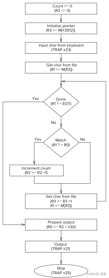
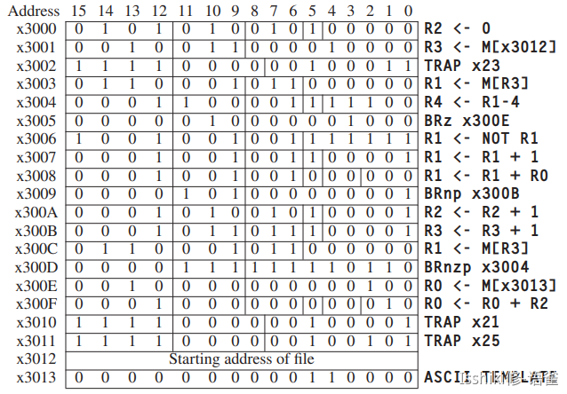
- Another Example: Counting Occurrences of a Character
- The Data Path Revisited
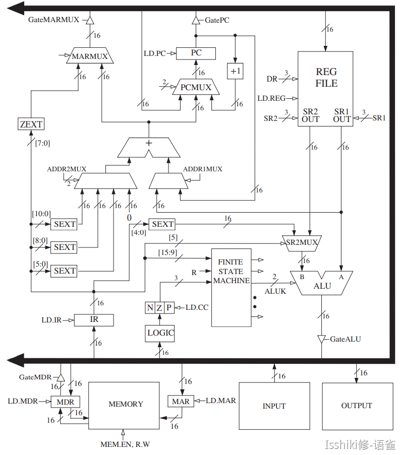
- Basic Components of the Data Path
- The Global Bus
- The LC-3 global bus consists of 16 wires and associated electronics. It allows one structure to transfer up to 16 bits of information to another structure by making the necessary electronic connections on the bus.
- Note that each structure that supplies values to the bus has a triangle just behind its input arrow to the bus. This triangle (called a tri-state device) allows the computer's control logic to enable exactly one supplier to provide information to the bus at any one time.
- The pros and cons of a single global bus is yet another topic that will have to wait for later in your education.
- Memory
- One of the most important parts of any computer is the memory that contains both instructions and data.
- Memory is accessed by loading the memory address register (MAR) with the address of the location to be accessed. To perform a load, control signals then read the contents of that memory location, and the result of that read is delivered by the memory to the memory data register (MDR). On the other hand, to perform a store, what is to be stored is loaded into the MDR. Then the control signals assert a write enable (WE) signal in order to store the value contained in MDR in the memory location specified by MAR.
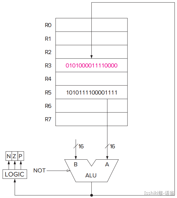
- The ALU and the Register File
- The results of an ALU operation are (a) a result that is stored in one of the registers, and (b) the three single-bit condition codes.
- The PC and the PCMUX
- The MARMUX
- The Instruction Cycle Specific to the LC-3
- FETCH
- DECODE
- EVALUATE ADDRESS
- OPERAND FETCH
- EXECUTE
- STORE RESULT