Review Chap 9
Privilege,Priority, and the Memory Address Space
Privilege: it is about the right to do something, such as execute a particular instruction or access a particular memory location.(NOTE: not all computer programs have the right to execute all instructions.)
To make the system go correctly, we designate every computer system as either privileged or unprivileged. We often say supervisor privilege to indicate privileged. We say a program is executing in Supervisor mode to indicate privileged, or User mode to indicate unprivileged.
- If a program is executing in Supervisor mode, it can execute all instructions and access all of memory.
- If a program is executing in User mode, it cannot.
Priority: it is about the urgency of a program to execute. This allows programs of greater urgency to interrupt programs of lesser urgency.
Two Orthogonal Notions
We said privilege and priority are two orthogonal notions, meaning they have nothing to do with each other.
The Processor Status Register
It contains the privilege and priority assigned to that program.

Bit 15 specifies the privilege, where PSR[15]=0 means supervisor privilege, and PSR[15]=1 means unprivileged. Bits[10:8] specify the priority level of the program. The highest level is 7 and the lowest level is 0. Besides, it also contains the condition code.
Organization of Memory

- Locations x0000 to x2FFF are privileged memory locations. They contain the various data structures and code of the operating system. They require supervisor privilege to access. They are referred to as system space.
- Supervisor Stack is controlled by the operating system and requires supervisor privilege to access. It has a stack pointer called SSP (Supervisor Stack Pointer).
- Locations x3000 to xFDFF are unprivileged memory locations. Supervisor privilege is not required to access these memory locations. All user programs and data use this region of memory. The region is often referred to as user space.
- User Stack is controlled by the user program and does not require privilege to access. It has a stack pointer called USP (User Stack Pointer).
- Addresses xFE00 to xFFFF do not correspond to memory locations at all. That is, the last address of a memory location is xFDFF. Addresses xFE00 to xFFFF are used to identify registers that take part in input and output functions and some special registers associated with the processor.
- PSR ~ xFFFC
- processor's Master Control Register (MCR)(clock cycle switch) ~ xFFFE
- KBSR KBDR DSR DDR ...
- 这些并不是实际内存,而是别映射过来的 Memory-mapped I/O !
- Since a program can only execute in Supervisor mode or User mode at any one time, only one of the two stacks is active at any one time.
- R6 is generally used as the SP for the active stack. Two registers, Saved_SSP and Saved_USP, are provided to save the SP not in use. When privilege changes, for example, from Supervisor mode to User mode, the SP is stored in Saved_SSP, and the SP is loaded from Saved_USP.
Input/Output
- Even the simplest I/O devices usually need at least two registers: one to hold the data being transferred between the device and the computer, and one to indicate status information about the device.
- An example of status information is whether the device is available or is it still busy processing the most recent I/O task.
- Some Basic Characteristics of I/O
Memory-Mapped I/O vs. Special I/O Instructions
- The I/O device registers are mapped to a set of addresses that are allocated to I/O device registers rather than to memory locations. Hence the name memory-mapped I/O.
- Special I/O Instructions are not so liked.
Asynchronous vs. Synchronous
- Most I/O is carried out at speeds very much slower than the speed of the processor.
- The point is that I/O devices usually operate at speeds very different from that of a microprocessor, and not in lockstep. We call this latter characteristic asynchronous. Most interaction between a processor and I/O is asynchronous.
- To control processing in an asynchronous world requires some protocol or handshaking mechanism. So it is with our keyboard and monitor.
- In the case of the keyboard, we will need a one-bit status register, called a flag, to indicate if someone has or has not typed a character.
- In the case of the monitor, we will need a one-bit status register to indicate whether or not the most recent character sent to the monitor has been displayed, and so the monitor can be given another character to display.
- These flags are the simplest form of synchronization.
- By examining the ready bit before reading a character, the computer can tell whether it has already read the last character typed.
Interrupt-Driven vs. Polling
- 🔗 Difference between an interrupt and a trap.
- The processor, which is computing, and the typist, who is typing, are two separate entities.
- The issue of interrupt-driven vs. polling is the issue of who controls the interaction.
- Interrupt-driven acts like that the typist will tell the processor that there are some inputs.
- Polling acts like that the processor will interrogate typist again and again whether there have some inputs.
- 中断是每当监控的设备发生变化,比如有输入的时候,就执行中断相关的代码片段;而轮询是指你主动去不断请求,检测监控的设备是否发生变化。
Input from the Keyboard
Basic Input Registers (KBDR and KBSR): KBDataR & KBStatusR
- In the case of KBDR, bits [7:0] are used for the data, and bits [15:8] contain
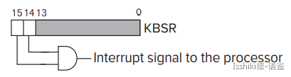
x00. - In the case of KBSR, bit [15] contains the synchronization mechanism, that is, the ready bit; and bit[14] is the interrupt enable bit, depending on whether or not the processor wants to give the I/O device the right to request service.
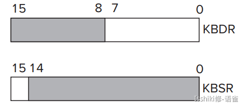
- In LC-3, address
xFE02is assigned to the KBDR; addressxFE00is assigned to the KBSR.
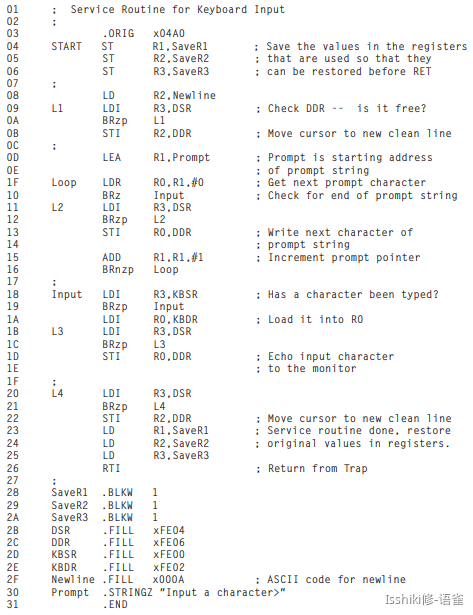
The Basic Input Service Routine
- When type in something, KBDR is updated and KBSR is set to
1. And KBDR can't be changed until KBSR is reset and the data in KBDR is read. So that each character can be loaded at least one time.
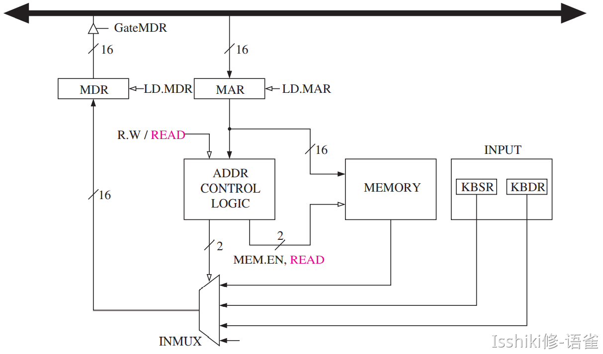
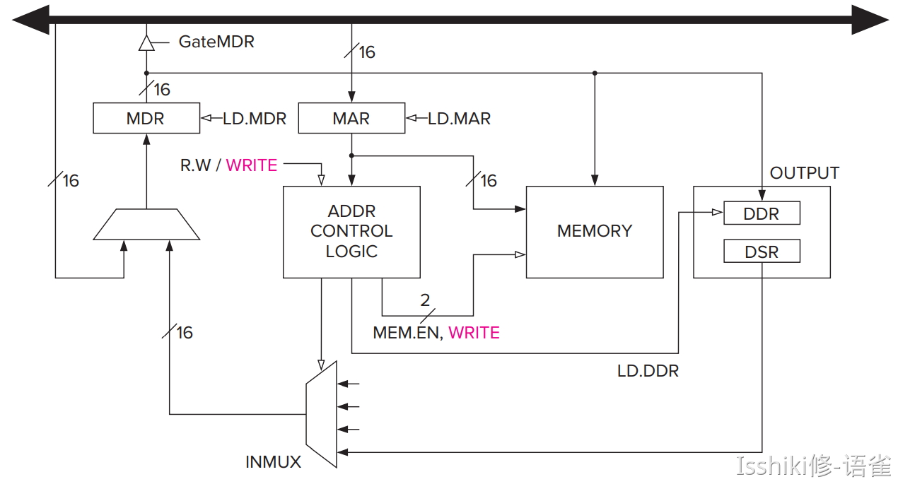
- Implementation of Memory-Mapped Input
Output to the Monitor(In fact very similar to the input)
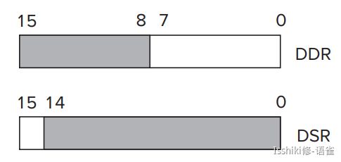
DDR and DSR replace KBDR and KBSR.
- In the case of DDR, bits [7:0] are used for data, and bits [15:8] contain
x00. - In the case of DSR, bit [15] contains the synchronization mechanism, that is, the ready bit.
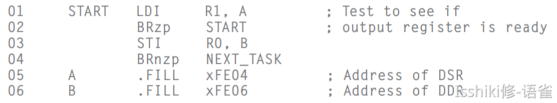
- In LC-3, address
xFE06is assigned to the DDR; addressxFE04is assigned to the DSR.
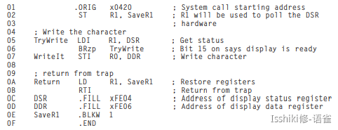
The Basic Output Service Routine
- When display something, DDR is updated and DSR is cleared. And DDR can't be changed until DSR is set to
1and the data in DDR is printed.
Implementation of Memory-Mapped Output

Operating System Service Routines (LC-3 Trap Routines)
- In general it is ill-advised to give user programmers access to these registers. That is why the addresses of hardware registers are part of the privileged memory address space and accessible only to programs that have supervisor privilege.
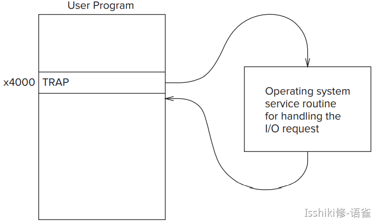
- The simpler solution, as well as the safer solution to the problem of user programs requiring I/O, involves the
TRAPinstruction and the operating system, which of course has supervisor privilege. - It (
TRAP) allows the user programmer to not have to know the gory details of I/O discussed earlier in this chapter. In addition, it protects user programs from the consequences of other inept user programmers. - The user program uses the
TRAPinstruction to request the operating system to perform the task on behalf of the user program. The operating system takes control of the computer, handles the request specified by theTRAPinstruction, and then returns control back to the user program at locationx4001. As we said at the start of this chapter, we usually refer to the request made by the user program as a system call or a service call.
The Trap Mechanism
- A set of service routines executed on behalf of user programs by the operating system. These are part of the operating system and start at arbitrary addresses in system space. The LC-3 was designed so that up to 256 service routines can be specified. Table A.2 in Appendix A contains the LC-3's current complete list of operating system service routines.
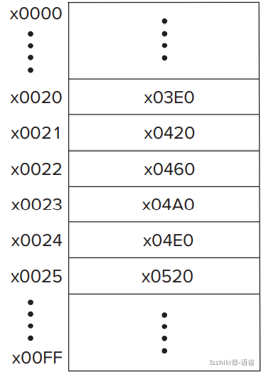
- A table of the starting addresses of these 256 service routines. This table is stored in memory locations x0000 to x00FF. The table is referred to by various names by various companies. One company calls this table the System Control Block. Another company calls it the Trap Vector Table. Figure 9.10 shows the Trap Vector Table of the LC-3, with specific starting addresses highlighted. Among the starting addresses are the one for the character output service routine (memory location x0420), which is stored in memory location x0021, the one for the keyboard input service routine (location x04A0), stored in location x0023, and the one for the machine halt service routine (location x0520), stored in location x0025.
- The
TRAPinstruction. When a user program wishes to have the operating system execute a specific service routine on behalf of the user program, and then return control to the user program, the user program uses the TRAP instruction. - A linkage back to the user program. The service routine must have a mechanism for returning control to the user program.
The TRAP Instruction
- The TRAP instruction causes the service routine to execute by:
- changing the
PCto the starting address of the relevant service routine on the basis of its trap vector; - providing a way to get back to the program that executed the
TRAPinstruction. The "way back" is referred to as a linkage; - As you know, the
TRAPinstruction is made up of two parts: theTRAPopcode 1111 and the trap vector (bits [7:0]), which identifies the service routine the user program wants the operating system to execute on its behalf. Bits [11:8] must be zero.

- The EXECUTE phase of the TRAP instruction's instruction cycle does three things:
- The PSR and PC are both pushed onto the system stack. Since the PC was incremented during the FETCH phase of the TRAP instruction's instruction cycle, the return linkage is automatically saved in the PC. When control returns to the user program, the PC will automatically be pointing to the instruction following the TRAP instruction. Note that the program requesting the trap service routine can be running either in Supervisor mode or in User mode. If in User mode, R6, the stack pointer, is pointing to the user stack. Before the PSR and PC can be pushed onto the system stack, the current contents of R6 must be stored in Saved USP, and the contents of Saved SSP loaded into R6.
- PSR[15] is set to 0, since the service routine is going to require supervisor privilege to execute. PSR[10:8] are left unchanged since the priority of the TRAP routine is the same as the priority of the program that requested it.
- The 8-bit trap vector is zero-extended to 16 bits to form an address that corresponds to a location in the Trap Vector Table. For the trap vector x23, that address is x0023. Memory location x0023 contains x04A0, the starting address of the TRAP x23 service routine. The PC is loaded with x04A0, completing the instruction cycle.
- The
RTIInstruction: To Return Control to the Calling Program - The
RTIinstruction (opcode = 1000, with no operands) pops the top two values on the system stack into the PC and PSR. Since the PC contains the address following the address of the TRAP instruction, control returns to the user program at the correct address. - Finally, once the PSR has been popped off the system stack,
PSR[15]must be examined to see whether the processor was running in User mode or Supervisor mode when the TRAP instruction was executed.
Trap Routines for Handling I/O
- A Trap Routine for Halting the Computer
Interrupts and Interrupt-Driven I/O
The essence of interrupt-driven I/O is the notion that an I/O device that may or may not have anything to do with the program that is running can(1) force the running program to stop,(2) have the processor execute a program that carries out the needs of the I/O device, and then(3) have the stopped program resume execution as if nothing had happened.
Interrupt-driven I/O do not waste time during input and output, instead, it can do useful work until it is notified that some I/O device needs attention.
Two parts to the process:
- The mechanism that enables an I/O device to interrupt the processor.
- The mechanism that handles the interrupt request.
Part I:
Three things must be true to allow an I/O device to interrupt the running program:
- The I/O device must want service: Check the ready bit in KBSR or DSR to confirm.
- The device must have the right to request the service: that is the interrupt enable (IE) bit. In KBSR and DSR it is in bit[14]. The interrupt request signal from the I/O device is the logical AND of the IE bit and the ready bit.

- The device request must be more urgent than what the processor is currently doing: it means the priority of the request must be higher than the priority of the program it wishes to interrupt.
The INT signal
To stop the processor from continuing execution of its currently running program and service an interrupt request, the INT signal must be asserted.
The picture shows the status registers of several devices operating at various priority levels (PL). Any device that has bits [14] and [15] both set asserts its interrupt request signal. The interrupt request signals are input to a priority encoder, a combinational logic structure that selects the highest priority request from all those asserted. If the PL of that request is higher than the PL of the currently executing program, the INT signal is asserted.

Finally, the test to enable the processor to stop and handle the interrupt. Recall from Chapter 4 that the instruction cycle continually sequences through the phases of the instruction cycle (FETCH, DECODE, EVALUATE ADDRESS, FETCH OPERAND, EXECUTE, and STORE RESULT). Each instruction changes the state of the computer, and that change is completed at the end of the instruction cycle for that instruction. That is, in the last clock cycle before the computer returns to the FETCH phase for the next instruction, the computer is put in the state caused by the complete execution of the current instruction. Interrupts can happen at any time. They are asynchronous to the synchronous finite-state machine controlling the computer. For example, the interrupt signal could occur when the instruction cycle is in its FETCH OPERAND phase. If we stopped the currently executing program when the instruction cycle was in its FETCH OPERAND phase, we would have to keep track of what part of the current instruction has executed and what part of the current instruction still has work to do. It makes much more sense to ignore interrupt signals except when we are at an instruction boundary; that is, the current instruction has completed, and the next instruction has not yet started. Doing that means we do not have to worry about partially executed instructions, since the state of the computer is the state created by the completion of the current instruction, period! The additional logic to test for the interrupt signal is to augment the last state of the instruction cycle for each instruction with a test. Instead of always going from the last state of one instruction cycle to the first state of the FETCH phase of the next instruction, the next state depends on the INT signal. If INT is not asserted, then it is business as usual, with the control unit returning to the FETCH phase to start processing the next instruction. If INT is asserted, then the next state is the first state of Part II, handling the interrupt request.
Part II:
Handling the interrupt goes through 3 stages:
- Initiate the interrupt.
- Service the interrupt.
- Return from the interrupt.
First: Initiate
There are two things to do:
- Save the state of the interrupted program: The first step is to save enough of the state of the program that is running so that it can continue where it left off after the I/O device request has been satisfied. That means storing current PC and PSR(These are the only state information LC-3 need to store during the execution).They are saved on the supervisor stack in the same way that PC and PSR are saved when a TRAP instruction is executed.
- Load the state of the interrupt service routine:
Once the state of the interrupted program has been safely saved on the supervisor stack, the second step is to load the PC and PSR of the interrupt service routine. Interrupt service routines are similar to the trap service routines we have already discussed. They are program fragments stored in system space. They service interrupt requests.
Most processors use the mechanism of vectored interrupts. You are familiar with this notion from your study of the trap vector contained in the TRAP instruction. In the case of interrupts, the eight-bit vector is provided by the device that is requesting the processor be interrupted. That is, the I/O device transmits to the processor an eight-bit interrupt vector along with its interrupt request signal and its priority level. The interrupt vector corresponding to the highest priority interrupt request is the one supplied to the processor. It is designated INTV.
If the interrupt is taken, the processor expands the 8-bit interrupt vector (INTV) to form a 16-bit address, which is an entry into the Interrupt Vector Table. You know that the Trap Vector Table consists of memory locations x0000 to x00FF, each containing the starting address of a trap service routine. The Interrupt Vector Table consists of memory locations x0100 to x01FF, each containing the starting address of an interrupt service routine. The processor loads the PC with the contents of the location in the Interrupt Vector Table corresponding to the address formed by expanding the interrupt vector INTV.
The PSR is loaded as follows: Since no instructions in the service routine have yet executed, PSR[2:0] contains no meaningful information. We arbitrarily load it initially with 010. Since the interrupt service routine runs in privileged mode, PSR[15] is set to 0. PSR[10:8] is set to the priority level associated with the interrupt request.
This completes the initiation phase, and the interrupt service routine is ready to execute.
Second: Service(OMIT)
Finally: Return
The last instruction in every interrupt service routine is RTI, which stands for "return from trap or interrupt". When the processor finally accesses the RTI instruction, all the requirements of the I/O device have been taken care of.